
Point: The TPA1864-TR advertises sub-millivolt input offset, a critical figure for precision front-ends. Evidence: the family datasheet highlights input offset ≤1 mV under specified conditions. Explanation: designers prioritize that offset number because it directly sets initial system error and the required calibration budget for high-precision sensor chains.
Point: This article decodes the published datasheet, aligns expected behavior with practical bench methods, and gives clear design guidance. Evidence: it pairs datasheet claims with recommended validation tests and layout tips. Explanation: the goal is to speed development for instrumentation, low-noise preamps, and precision buffering by translating datasheet items into repeatable engineering actions.
1 — Overview & Key Use Cases (background)
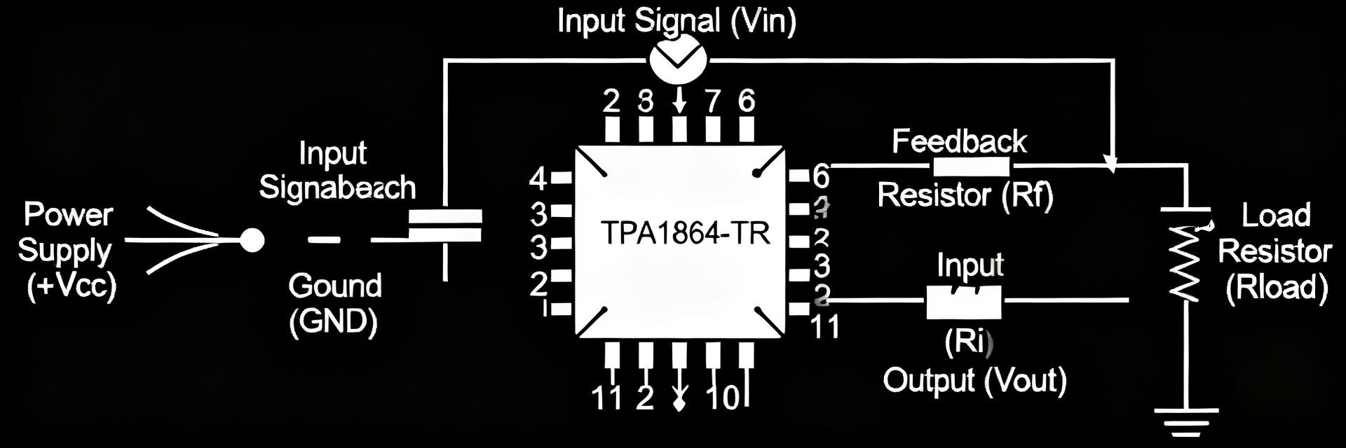
1.1 — What the device is and where it fits
Point: The device is a precision operational amplifier intended for low-offset applications.
Evidence: per the datasheet, the family emphasizes low input offset and precision bias behavior across standard single-supply ranges.
Explanation: typical application domains include precision instrumentation, sensor front-ends, low-noise audio preamps, and reference buffering where millivolt-level errors are consequential.
1.2 — Top-level spec snapshot (quick reference)
| Core Analysis | Details |
|---|---|
| Point | Designers need an at-a-glance spec list before deeper analysis. |
| Evidence | The datasheet calls out the most critical parameters: input offset (≤1 mV), low input bias current, low input noise floor, moderate gain-bandwidth, controlled slew rate, and practical output swing versus supply. |
| Explanation | Use this snapshot to filter suitability quickly—if offset, noise, or drive don’t meet system budgets, investigate alternatives or compensation early. |
2 — TPA1864-TR Detailed Specs Deep-Dive (data analysis)
2.1 — Precision parameters: offset, drift, noise
Point: Offset, drift, and noise define DC and low-frequency system accuracy.
Evidence: the datasheet lists typical and max offset values and notes thermal drift behavior in the electrical characteristics table.
Explanation: to reproduce datasheet offset figures, measure with low-noise, low-leakage fixturing, tight source grounding, and averaging; for noise, use a low-noise source and specify bandwidth when quoting nV/√Hz performance.
2.2 — Dynamic performance: bandwidth, slew rate, stability margins
Point: Bandwidth and slew rate determine closed-loop response and large-signal behavior.
Evidence: the datasheet reports small-signal bandwidth and slew-rate specifications alongside recommended test conditions and load.
Explanation: when selecting gain or feedback networks, compute gain-bandwidth product limits, confirm phase margin at intended closed-loop gain, and add feedforward or compensation if margins shrink under capacitive loads.
3 — Benchmarks & Test Results (data analysis / methods)
3.1 — Recommended benchmark tests and metrics
Point: A focused bench plan validates datasheet claims and reveals integration risks.
Evidence: run input offset and noise floor tests, Bode plots for frequency response, THD+N for audio paths, settling-time, CMRR, and PSRR under the datasheet’s supply conditions—these form the core benchmarks.
Explanation: document VCC, RL, source impedance, and measurement bandwidth for each test so results map back to the datasheet conditions and are reproducible across labs.
3.2 — Interpreting real-world deviations from the datasheet
Point: Bench outcomes often differ from published numbers; understanding causes prevents misdiagnosis.
Evidence: common contributors include PCB parasitics, load impedance differences, temperature variance, and bandwidth limits in test equipment.
Explanation: isolate variables by reverting to the datasheet’s recommended fixture, shorten input leads, add proper decoupling, and repeat tests to determine if deviations are device-specific or system-induced.
4 — Application Comparisons & Integration Examples (case study)
4.1 — Typical application circuits
Point: The amplifier is well suited for buffers, low-noise preamps, and difference amplifiers with trade-offs between noise and bandwidth.
Evidence: in unity-gain buffer and noninverting preamp topologies, the datasheet’s offset and noise figures drive component selection.
Explanation: use low-value feedback resistors for lower Johnson noise, include a small series input resistor to stabilize against capacitive loads, and choose resistor types (metal-film) for low tempco.
4.2 — In-system comparison
Point: In-system comparison should focus on thermal behavior, supply headroom, and output drive under actual loads.
Evidence: the datasheet specifies output swing and recommended supply ranges that set practical headroom limits for common-mode and rail-to-rail requirements.
Explanation: if system tests show margin issues, evaluate alternatives with higher GBW or rail-to-rail output, or redesign the power rail scheme to preserve dynamic range.
5 — Design Checklist & Troubleshooting (action)
5.1 — Pre-layout checklist before prototype
Point: A short checklist prevents common pitfalls before first prototype.
Evidence: verify required supply rails and headroom against the datasheet, plan decoupling close to the device, choose low-noise resistors, and add input protection if the front-end may see transients.
Explanation: place bypass caps within millimeters of supply pins, use star grounding for sensitive inputs, and document measurement nodes for quick validation on initial builds.
5.2 — Common issues and fixes
Point: Rapid isolation and fixes save prototype cycles.
Evidence: symptoms like oscillation, elevated noise, or bias shifts often trace to layout, inadequate decoupling, or unexpected source impedance.
Explanation: immediate fixes include adding a small series resistor at the input, improving bypassing, reducing feedback resistor values, or adding a compensating capacitor across the feedback to tame high-frequency gain.
Key Summary
- TPA1864-TR delivers sub-millivolt offset, making it a strong choice where low DC error is essential; confirm offset and drift against the datasheet during bench validation to set calibration budgets.
- Focus benchmarks on input noise, frequency response, and settling time under documented VCC and RL conditions to ensure real-world behavior matches specifications.
- Before prototype, follow the pre-layout checklist—power decoupling, low-noise resistor choices, and guarded inputs—to avoid common integration pitfalls and speed debugging.
Summary
Point: Translating key datasheet numbers into concrete validation steps reduces risk.
Evidence: by pairing measured benchmarks with the datasheet’s stated conditions and using the checklist and troubleshooting tips above, engineers can confirm suitability efficiently.
Explanation: run the recommended tests, monitor deviations carefully, and iterate layout and compensation to achieve the expected precision performance.
Common Questions
What measurement setup reproduces the datasheet offset and noise numbers?
Use a low-noise, low-leakage fixture with the amplifier in the intended topology, stable regulated supplies, and shielded cabling. Average multiple measurements, narrow measurement bandwidth to the datasheet’s test bandwidth, and report source impedance and ambient temperature alongside results for reproducibility.
Which benchmarks should be prioritized for low-noise instrumentation?
Prioritize input-referred noise density, offset and drift, and wideband THD+N as primary benchmarks. Also measure PSRR and CMRR in the intended supply and common-mode ranges. Those results determine whether the front-end meets noise floor and accuracy targets.
How do I isolate oscillation vs system-induced instability?
First, add a small series resistor at the input and a bypass capacitor across the feedback to damp potential HF peaking. Test with the amplifier removed or replaced by a known-good part to see if the symptom persists; if it does, the issue is system-related—check grounding and decoupling.


