
LM2903A-VR Complete Datasheet Breakdown & Pinout Guide
The LM2903A-VR is a low-power dual comparator rated for operation up to 36 V with a common‑mode input range that includes ground and open‑collector outputs, making it suitable for battery‑powered threshold and protection circuits. This datasheet-driven walkthrough translates key tables and pinout details into immediately actionable guidance for design and test.
This guide targets practical decisions: how to read absolute maximums and recommended conditions, translate electrical characteristics into wiring and component choices, and verify behavior on the bench.
Overview: What LM2903A-VR Is and Where It Fits
Device summary and key selling points
The LM2903A-VR is a dual, single‑supply comparator optimized for low quiescent current and robust rail‑to‑ground sensing; its open‑collector outputs require external pull‑ups and allow level shifting to different logic voltages.
- Supply range: single supply up to 36 V (max rating)
- Supply current: low quiescent current per comparator
- Output stage: open‑collector (requires pull‑up)
- Input: common‑mode includes ground
- Temperature: industrial commercial ranges supported
When to choose this comparator (application fit)
Choose this comparator for battery monitors, threshold detectors, window comparators, watchdog circuits, and simple level shifting where speed is not critical. The LM2903A‑VR trades switching latency for lower power and wider input/supply margins.
Datasheet Deep Dive: Electrical Specifications & Performance
Absolute maximum ratings & recommended operating conditions
When reading absolute maximums, treat them as limits to avoid permanent damage. Recommended operating conditions provide safe, reliable margins for long‑term performance.
Key electrical characteristics explained
Important specs to translate to design are input offset voltage, input bias currents, common‑mode range, and propagation delay. Open‑collector outputs do not drive high; choose pull‑ups to set the high level and trade speed versus quiescent current accordingly.
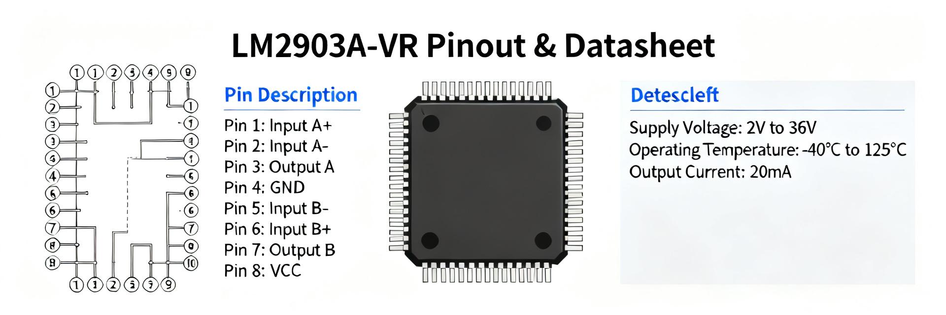
Pinout & Functional Description (LM2903A-VR)
Pin-by-pin breakdown and common package options
Typical dual comparator pinouts use an 8‑pin package. Pin numbering can vary—verify package drawing before routing.
| Pin | Name | Function / Wiring note |
|---|---|---|
| 1 | Output A | Open‑collector; add pull‑up to logic rail |
| 2 | In A− | Inverting input; can be tied to divider/hysteresis network |
| 3 | In A+ | Non‑inverting input |
| 4 | GND | Ground reference; use solid return |
| 5 | In B+ | Non‑inverting input for comparator B |
| 6 | In B− | Inverting input for comparator B |
| 7 | Output B | Open‑collector output B |
| 8 | VCC | Supply; decouple close to pin |
Typical Applications & Practical Design Examples
Common reference circuits
Example 1: Threshold comparator with hysteresis—use positive feedback to avoid oscillation.
Example 2: Level shifting—tie pull‑ups to MCU rail for 3.3V/5V compatibility.
Example 3: Window detector—bracket upper and lower thresholds for battery protection.
- Hysteresis calc: Vth ≈ Vref × Rlower/(Rupper+Rlower); pick R values 10 kΩ–100 kΩ.
- Level shift: pull‑up to 3.3 V or 5 V depending on target logic.
Power supply, decoupling, and EMI considerations
Place a 0.1 μF ceramic decoupling capacitor within 5 mm of VCC pin. For EMI, add small series resistors (47–220 Ω) at inputs and use ESD diodes at connectors to prevent overstress.
Testing, Troubleshooting & Best Practices
Bench test checklist
- Verify VCC and ground wiring, decoupling placement.
- Check pull‑up resistor values and resulting VOH/ VOL.
- Measure offset and propagation delay with proper technique.
Common failure modes
- Oscillation: No hysteresis or long wiring.
- Stuck low: Overcurrent or short circuit.
- Logic error: Incorrect pull‑up voltage.
Summary
The LM2903A-VR is a practical low‑power, wide‑supply dual comparator with open‑collector outputs. This guide equips engineers to wire the correct pinout, implement hysteresis, and perform bench verification.
- Wide VCC tolerance (up to 36 V).
- Design for speed/power tradeoff with pull‑up resistors.
- Always confirm stable VCC ramp and input common-mode limits.
FAQ — Common questions about LM2903A-VR
What pull‑up resistor should I use with LM2903A‑VR for 3.3 V logic?
For 3.3 V logic, a 10 kΩ pull‑up is a practical starting point. If you need faster edges, reduce to 4.7 kΩ or 2.2 kΩ, noting increased power consumption.
Can the inputs exceed the supply rails on the LM2903A‑VR?
Inputs should not be driven far beyond the supply rails. Use series resistors and external clamp diodes when signals may exceed rails to prevent damage.
How do I add hysteresis for a noisy threshold using this comparator?
Add positive feedback from the output to the non‑inverting input via a resistor divider (typically 10 kΩ–100 kΩ) so the switching threshold shifts depending on the output state.


