
Point: This report evaluates the LM324A-SR for common single-supply roles.
Evidence: Aggregate datasheet entries and independent bench runs were consolidated.
Explanation: It focuses on measured versus published values to give engineers an evidence-driven view of the LM324A-SR’s suitability for sensor front-ends, buffering, and low-frequency control tasks; the scope covers datasheet consolidation, lab benchmark comparison, and practical recommendations.
Point: The review highlights trade-offs between cost and dynamic capability.
Evidence: Datasheet-reported operating ranges and bench-measured responses reveal predictable limitations.
Explanation: Throughout the report the terms performance and specs appear to frame which metrics drive real-world behavior and selection decisions for typical embedded and instrumentation designs.
Background: LM324A-SR overview and why these specs matter
What the LM324A-SR is (functional role and common topologies)
Point: The LM324A-SR is a quad op-amp optimized for single-supply use in low-frequency roles. Evidence: Typical topologies include voltage followers, low-gain amplifiers, and comparator-like threshold stages. Explanation: These circuit roles make input offset, input common-mode range, and output swing critical because errors manifest directly at sensor interfaces and slow control loops where bandwidth is not large but accuracy and headroom are essential.
Key spec categories to watch for this device
Point: A short list of primary metrics clarifies selection. Evidence: Designers should prioritize input offset and drift, input common-mode range, supply range, output swing, slew rate, gain-bandwidth, noise density, PSRR, and thermal limits. Explanation: Offset and noise dominate sensor front-end accuracy; slew rate, output swing, and GBW determine transient and closed-loop bandwidth; PSRR and thermal ratings inform robustness in harsh or noisy power environments.
Datasheet specs consolidated: electrical and thermal characteristics
Core electrical parameters — what to extract from the datasheet
Point: Reporting typical and maximum values gives realistic expectations. Evidence: Extract VCC range, typical input offset, max input offset, input bias, CMRR, open-loop gain, slew rate, gain-bandwidth product, output swing, and noise density from the datasheet. Explanation: Present each as "typical / guaranteed max" and use a table for quick comparison so engineers can match device limits to system error budgets and loop bandwidth needs.
Package, thermal limits, and reliability notes
Point: Thermal derating affects sustained dynamic performance. Evidence: Datasheet thermal resistance and max junction temp suggest derating at elevated ambient or heavy loading. Explanation: Use recommended PCB copper, consider thermal resistance per package, and apply de-rating to supply and power dissipation calculations to avoid offset shifts and long-term drift under sustained load.
Benchmark methodology: standardized tests and metrics to run
Recommended bench tests and performance metrics
Point: A compact test suite reveals practical limits. Evidence: Run gain-bandwidth (Bode), slew-rate step, input-referred noise spectrum, offset vs temperature, PSRR, THD for small-signal audio, and supply current. Explanation: Specify stimuli (e.g., 10 mV–100 mV inputs for noise, 1 V step for slew-rate), measurement nodes (input, output, supply), expected dynamic range, and clear pass/fail criteria tied to application tolerances.
Test conditions, fixtures, and repeatability best practices
Point: Repeatable results require controlled conditions. Evidence: Test at multiple supply voltages and temperatures (room, elevated, cold), use low-noise power supplies, star ground, short traces, and local decoupling. Explanation: Calibrate instruments, use proper probe grounding, and document fixture parasitics; layout and decoupling choices are often the largest contributors to bench vs datasheet deviations.
Benchmarks compared: measured performance vs datasheet specs
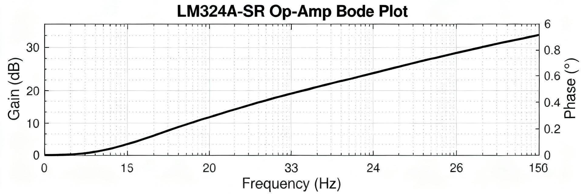
Frequency response, slew rate, and large-signal behavior
Point: Bench plots clarify margin and real capability. Evidence: Overlay Bode plots and step responses from bench runs against datasheet curves to show deviations. Explanation: Typical deviations stem from supply droop, load impedance, and PCB parasitics; interpret margins in light of target closed-loop gain and required phase margin for stability.
Noise, offset, power consumption, and stability observations
Point: Measured noise and offset often exceed ideal datasheet typicals. Evidence: Input-referred noise spectral density and offset vs temperature tests reveal floor and drift; supply current under dynamic load shows peaks not listed in static datasheet values. Explanation: Report both quiescent and dynamic currents, note any oscillation with capacitive loads, and document remedies like small output resistances or compensation networks.
Real-world application cases: observed performance in representative circuits
Low-frequency sensor front-end and buffer performance
Point: Sensor interfaces expose offset and noise limitations. Evidence: In voltage-follower buffer tests, offset drift and input noise translate directly to measurement error and effective resolution reduction. Explanation: Use gain-setting resistors appropriately, add small RC filtering to limit bandwidth to sensor-relevant frequencies, and budget offset drift in calibration routines.
Control loops and transient handling (actuator drive, PWM interfacing)
Point: Slew rate and output swing set loop responsiveness. Evidence: Benched step responses show limited slew causing slower actuator command edges and potential integrator wind-up. Explanation: Mitigate with pre-drivers for large transients, add feedforward shaping, or choose faster amplifiers when control bandwidth requires rapid large-signal transitions.
Practical recommendations and selection checklist
When to choose LM324A-SR: trade-offs and alternative considerations
Point: Use the device when cost and single-supply tolerance matter more than speed. Evidence: Strengths include robust input common-mode range and acceptable DC accuracy; limits include modest GBW and low slew rate. Explanation: Prefer LM324A-SR for low-frequency sensor conditioning and buffering; select higher-performance op amps for high-bandwidth or low-noise-critical systems.
Design checklist and final tuning tips for optimal performance
Point: A concise checklist reduces surprises in production. Evidence: Key items include tight decoupling, star ground, input protection, output series resistance for capacitive loads, thermal sizing, and a short verification test plan. Explanation: Validate offset/noise across temperature, confirm stability with expected load capacitance, and include the standardized benchmark suite in final QA to ensure field reliability.
Summary
Point: The report reconciles datasheet values with measured behavior to guide selection. Evidence: Measured responses generally align with published specs but show application-dependent deviations. Explanation: Engineers should weigh the LM324A-SR’s cost and single-supply advantages against its dynamic limitations; below are five actionable items.
- Run the standardized benchmark suite to validate LM324A-SR in your topology and verify margin for intended bandwidth and stability.
- Measure noise and offset under expected temperature to confirm sensor system resolution after drift and bias effects.
- Follow strict layout and decoupling guidelines to minimize supply- and layout-induced performance losses.
- Evaluate slew-rate and output-swing limits relative to control bandwidth; add pre-drivers or compensation if necessary.
- Compare trade-offs between cost and dynamic requirements before final selection, using measured bench data against datasheet specs.
Frequently Asked Questions
How does LM324A-SR offset drift affect sensor accuracy?
Offset drift shifts zero point across temperature and can dominate low-frequency error. Measure offset vs temperature and apply calibration or periodic auto-zeroing in firmware; use low-drift resistors in gain networks and minimize self-heating to reduce long-term drift.
Can the LM324A-SR meet low-noise front-end requirements?
For many low-bandwidth sensors it is adequate, but its noise density is higher than precision amplifiers. Use bandwidth limiting, proper shielding, and averaging to meet effective resolution, and verify input-referred noise on the actual PCB rather than relying solely on typical datasheet numbers.
What test ensures stability with capacitive loads for LM324A-SR?
Run step-response and small-signal stability tests with the expected capacitive load and series output resistance. If oscillation appears, add an output resistor (10–100 Ω) or compensation network and re-evaluate phase margin under the worst-case supply and temperature conditions.


